|
 |
|||||||||||||||||||||||||||
 |
Operational TheoryThe Variloc creates its locking action by acting like a wedge system, with the ramp being the wedge, and the engine or braking torque being the hammer that acts on the wedge. Each ramp is actually two wedges, with one acting under acceleration and the other under deceleration. The locking rate produced is both in direct reaction to the torque input (without input torque there is no locking) as well as in direct proportion to the torque input (the more torque put into it, the harder it will lock up). The angles of each side of the ramp can be changed to create different locking rates and can be changed individually, so that changes to corner entry locking does not affect corner exit locking. Preload can be added to the assembly to assure that a desired minimum locking rate is available at all times, even when coasting. This adjustability allows the driver to fine-tune the differential action to every possible need, whether it be a high-bank oval, a flat dirt bullring, or a road course. Variloc 30x70 Main
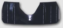
Ramp Internal Blow-up
Basics Torque from the engine is transferred from the ring gear to the main body and then to the ramp through the drive pins or the body bolts. The ramp drives the spider gears, which in turn drive the side gears and axles. The ramp is in angular contact with the spider gears. This contact forces the ramps to thrust sideways and clamp down on the clutches. The clutches are stacked so that every other clutch is splined either to the main housing or to the side gear. As the ramp clamps down on the clutches, torque from the main housing flows through the clutches to the side gear and axle, causing the "limited slip" or "locking" action. By varying the angles cut into the ramp where they contact the spider gears, one achieves different amounts of locking action. Additionally, the locking action for power on and power off can be independently tailored to suit the car's needs. Locking action is very smooth as it also varies with the amount of torque generated by the engine.
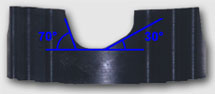
Side View Diagram of Ramp and Spider Gear
Ramp Angles Ramp angles are stated as the drive angle followed by the coast angle. The angle number stands for the direction in degrees of the ramp surface compared to the direction of the thrust - the lower the number, the greater the locking action.
Ramps can be purchased cut to almost any angle desired. Please consult with us before ordering ramps of non-standard angles.
Some Standard Ramps
|
|||||||||||||||||||||||||||